|
Some
systems were designed to be used for shipboard operational purposes
only (i.e., for determination of proper trim and stability and cargo
loading/discharging). Accordingly, both parties should be
aware of the limitations of any shipboard measurement system and agree
on the method of measurement to be used to determine the "official"
custody transfer volumes.
If
a closed or restricted measurement system is to be used for marine
custody transfer measurements, the accuracy of the equipment used
should fall within the tolerances set forth in API MPMS Chapters 2.8,
3.1A, 3.4, 7.3, and 7.4. However, because of various vessel
designs, and physical installation of the equipment used, accuracies
other than those described therein may be the maximum achievable. The
measurement accuracies designed into the system must be warranted by
the manufacturer.
MANUAL CLOSED AND RESTRICTED SYSTEMS
This
section describes the equipment to be used and the procedures to be
followed when measuring cargoes on ships that have manual closed or
restricted systems.
Manual Closed and Restricted
Equipment
Manual
equipment consists of a Portable Measurement Unit (PMU) which must be
carried from tank to tank to obtain the appropriate measurements
through a Vapor Control Valve (VCV) located at each tank. Generally,
PMUs and VCVs made by the same manufacturer are designed to be used
together. However, equipment made by different manufacturers
may be used together with an appropriate adapter.
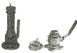
Vapor Control Valve
 These valves are generally
found on standpipes, flanges, existing ullage hatches, expansion
trunks, or fitted flush to the vessel's deck. These valves are generally
found on standpipes, flanges, existing ullage hatches, expansion
trunks, or fitted flush to the vessel's deck.
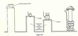
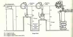
Note:
is an illustration of a vessel that has been retrofitted for a PMU
gauge location using existing gauge tables for "open" measurements.
They are designed to allow attachment of the portable measurement or
sampling device using a securing device or adaptor. By
operating
the VCV according to the manufacturer's instructions, the PMU probe,
sampler tape, and/or sampler can be lowered into the tank through the
VCV whether the vessel's inert gas system (lGS) is putting positive
pressure into the tanks or not.
Vapor
control valves come in varying diameters from 1 in. (25.4 mm) to 4 in.
(101.6 mm). The valve sizes and types are specified by the
manufacturer and the vessel owner. However, if the VCV is too narrow,
it will not allow adequate sampling to be conducted.
The
location and size of the VCV is critical to the ability to be able to
measure tank contents and to take sufficient samples. In
order to
be able to measure small quantities in a tank when the vessel is not on
an even keel, a VCV must be located as close as possible to the
bulkhead that is in the direction of the vessel's normal operating trim
and list when the vessel is in an OBQ/ROB condition. In
placing
the VCV, care must be given to assure its location will not cause the
measurement equipment to touch the tank bulkhead when in use.


It
may be noted that since many vessels have been retrofitted with vapor
control valves that are not in the exact location as the existing
"open" gauge points, tank capacity tables should be adjusted to take in
consideration any new gauge location for PMU equipment. Also, the vapor
control valve locations should be placed in accordance MPMS Chapter
2.8B. If the tables have not been adjusted for these location
changes, some corrective action may have to be taken to obtain correct
measurements. Such corrective action must take into
consideration
the use of adapters that allow the use of different manufacturers'
portable measurement units with varying vapor control configurations.
Sections of text taken from API - MPMS Chapter 17 Marine Measurement
|