|
Note I: This method may not be
applicable to pipeline systems with extensive horizontal
sections since gases may remain in these sections.
Note 2: Should the high-point bleed-valve
method be selected, valves designated for this operation
should be identified.
Note 3: Product flowing through a
pipeline system while valves are being bled may cause
existing air pockets to move past the bleed point.
Sight-glass connections should be at the
top and bottom of the pipeline circumference and should
permit convenient visual observation. If
sight-glass systems do not enable bleeding to evacuate
gases seen in the sight glass, one of the alternate
verification methods should be selected.
All appropriate valves between the
designated shore tank and the vessel berth should be
open and under sufficient positive pressure to permit
the line to be filled with liquid.
Appropriate action should be taken to
ensure that any venting of vapours or release of-liquids
during bleeding operations is safely controlled and
contained in accordance with applicable regulations.
The operation of high-point valves or
sight glasses should be performed by terminal personnel
and should be witnessed by authorized parties interested
in custody-transfer measurements.
To apply the high-point bleed-valve
method (or the sight-glass method), perform the
following steps consecutively.
Step 1 - Before opening high-point bleed
valves, ensure that lines are under positive pressure
at bleed positions.
Step 2 - Place an appropriate container
under each valve opening to receive liquid.
Step 3 - Slowly open the valve and allow
it to remain open until liquid appears in a steady
stream.
Note: Allow adequate time between the
bleedings of any two valves for gas to collect at the
bleed points.
Step 4 - Close the valve and proceed to
the next bleed valve.
Step 5 - Bleed each valve in the same
manner until all valves are bled.
PROCEDURES FOR PIGGING METHOD
The pigging method is an acceptable
method only when the terminal is fitted with the
launching and retrieving systems designed for this
purpose.
In the pigging method, a tight-fitting
wiping device (or "pig") is placed in a launching system
and then pushed through the designated pipeline system
with liquid, gas, or air. The original contents of
the pipeline system are therefore completely displaced
by the air, gas, or liquid used to propel the pig
through the line.
All pigs should be accounted for after
use. The operation should be repeated when pigs
are lost or damaged in pipelines.
The pigging method may be executed
before, after, or both before and after a cargo
transfer. If the pigging method is executed only
before a transfer, the volume of the pipeline must be
added to the cargo transfer volume.
PROCEDURE FOR LINE PRESS METHOD (OR LINE
PACK METHOD)
This procedure assumes that the
designated pipeline system is tight and able to
withstand pressures applied during line press operations
without loss of line pressure as determined by pressure
readings from a calibrated pressure gauge. This
procedure is invalid with any pipeline system that does
not meet this tightness recommendation.
To apply the line press method (or the
line pack method), perform the following steps
consecutively.
Step 1 - Close the valve at the dock
manifold. Open the shore tank and pump valves,
and gauge the tank before line press.
Measurements may be taken using either reliable
automatic gauging equipment or manual measurement
equipment.
Step 2 - Start the pump and run it until
the discharge pressure stabilizes and/or reaches a
predetermined pressure. The predetermined
pressure should be higher than the maximum static
pressure available on the system.
Step 3 - Isolate the pipeline to prevent
backflow and stop the pump.
Step 4 - Once the pump has been shut
down. record the pressure and re-gauge the tank using
the same gauging method as that used for the opening
measurements. Record the tank product level.
Step 5 - If the tank product levels
before and after the line press are within 1/8th
inch (3 millimeters) of one another, pipelines may be
considered liquid-full and no correction is necessary.
Step 6 - If the tank liquid levels before
and after the line press differ from one another by
more than 1/8th
inch (3 millimeters), relieve the line pressure into
the tank until the pressure at the highest elevation
is slightly above product vapour pressure and then
repeat the test. If the tank product levels
before and after the second line press differ from one
another by less than 1/8th inch (3
millimeters), pipelines are now full of liquid because
condensible vapours have been re-liquified and no
further correction is necessary.
Step 7 - If the tank liquid levels before
and after the second line press differ from one
another by more than 1/8th inch (3
millimeters), either the line fill condition may be
corrected by one of the alternate methods listed
earlier or - with the agreement of all parties - gas
volumes may be estimated by procedures and
calculations outlined in the Appendix.
Step 8 - For purposes of line fill
verification, the designated pipeline system may be
considered full if the difference between the volume
gauged before line press and the volume gauged after
line press is within measurement precision.
Note: This does not ensure that voids
equal to compressed gas volumes less than measurement
precision do not exist in the line.
LINE VERIFICATION AFTER CARGO TRANSFER
After cargo has been transferred, the
fullness condition of shore pipelines should be
determined by the application of any method outlined
earlier other than the line displacement method.
Establishing Agreed Tolerances
The three methods that require
calculation of the line fill condition are
-
the line displacement method,
-
the inter- nal circulation method, and
-
the line press method (or line pack
method).
With each of the three methods, two
measurements of the contents of each tank used are
taken: one measurement is taken before liquid is pumped
through or pressured in the designated pipeline system,
and one is taken after.
Note: The precision of the measurement
for each tank-regardless of whether it's a vessel lank
or a shore tank -is 1/8th
inch (3 millimeters). To agree on tolerances applicable
to comparing volumes between opening and closing
procedures, both the measurement precision limits above
and the historical vessel-to-shore line displacement,
internal circulation, or line press experiences should
be considered. The factors listed under General
Procedures should be considered as possible influences
on measurement tolerances. Special situations such
as those involving temperature variations between line
contents and tanks, the effect of volumetric shrinkage,
and product quality differences should also be
considered
APPENDIX-LINE PRESS (OR LINE PACK) COMPUTATION
1.
General
1.1 With the agreement of all parties,
the following procedures may be used when a second line
press, as outlined earlier, has resulted in a change in
tank liquid level of more than 1/8th
inch (3 millimeters). The purpose of the
calculation is to estimate the additional liquid volume
equivalent to those trapped gases that might not have
been condensed or re-liquified during the first of the
two line press procedures.
1.2
Calculating the volume of gas coexisting with liquid after a line
press yields an estimate of the gas volume when methods
that would displace or remove trapped gases are
undesirable or impractical. The calculation is
based on accepted physical ideal gas laws and is subject
to certain assumptions and limitations, which are listed
in '2'.
2.
Assumptions and Limitations
2.1 This procedure assumes that the
designated pipeline system is tight and able to
withstand pressures applied during line press operations
without loss of line pressure as determined by readings
from a calibrated pressure instrument. This
procedure is invalid with any pipeline system that does
not meet this tightness requirement.
2.2
Calculations in this procedure assume that the pressures
observed and used are representative of pressures
occurring within a gas bubble inside a partially filled
pipeline. Therefore, accuracy will be affected by
liquid hydrostatic head pressure (if any) between the
high point on the pipeline and the point of pressure
readings. If pipeline elevation varies by a
significant amount, then either the pressure instrument
should be installed at the highest possible elevation
point on the designated pipeline system or a hydrostatic
head pressure correction should be applied.
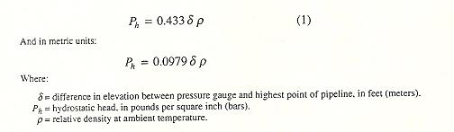
Note: If the pressure gauge location is
lower than the highest point on the pipeline system. a
correction for hydrostatic head should be added to the
required vapor pressure. The calculation for this
correction is as follows in English units:
2.3 The effects of heat of compression on
the gas bubble(s) remaining after the line press need
not be considered because of the impracticality of
determining the temperature of trapped gases and the
relative complexity of calculation. These effects
are minimized by the low mass (weight) of air relative
to that of the liquid (in the range from 50: 1 to 200:
I), the rapid air-to-steel heat transfer, and the fact
that a single compression stroke is per- formed.
The effect is further minimized if sufficient time is
allowed after compression or until pressure stabilizes
to permit heat equalization with the pipe walls. Several
minutes (or possibly longer in large diameter pipes)
should be sufficient time.
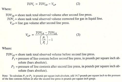
3. Calculations
The volume of the gas coexisting with
liquid in a designated pipeline system may be calculated
using data collected during line press operations as
indicated in the following equations:
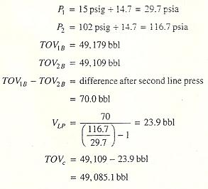
4.
An Example
The following example uses Equations 2.
and 3 to calculate the shore tank-total observed volume
corrected for gas in liquid line:
Sections of text taken from API - MPMS Chapter 17 Marine
Measurement
|